PCBs
If you would like an interactive look at our project schematics and board files.
Upper PCB
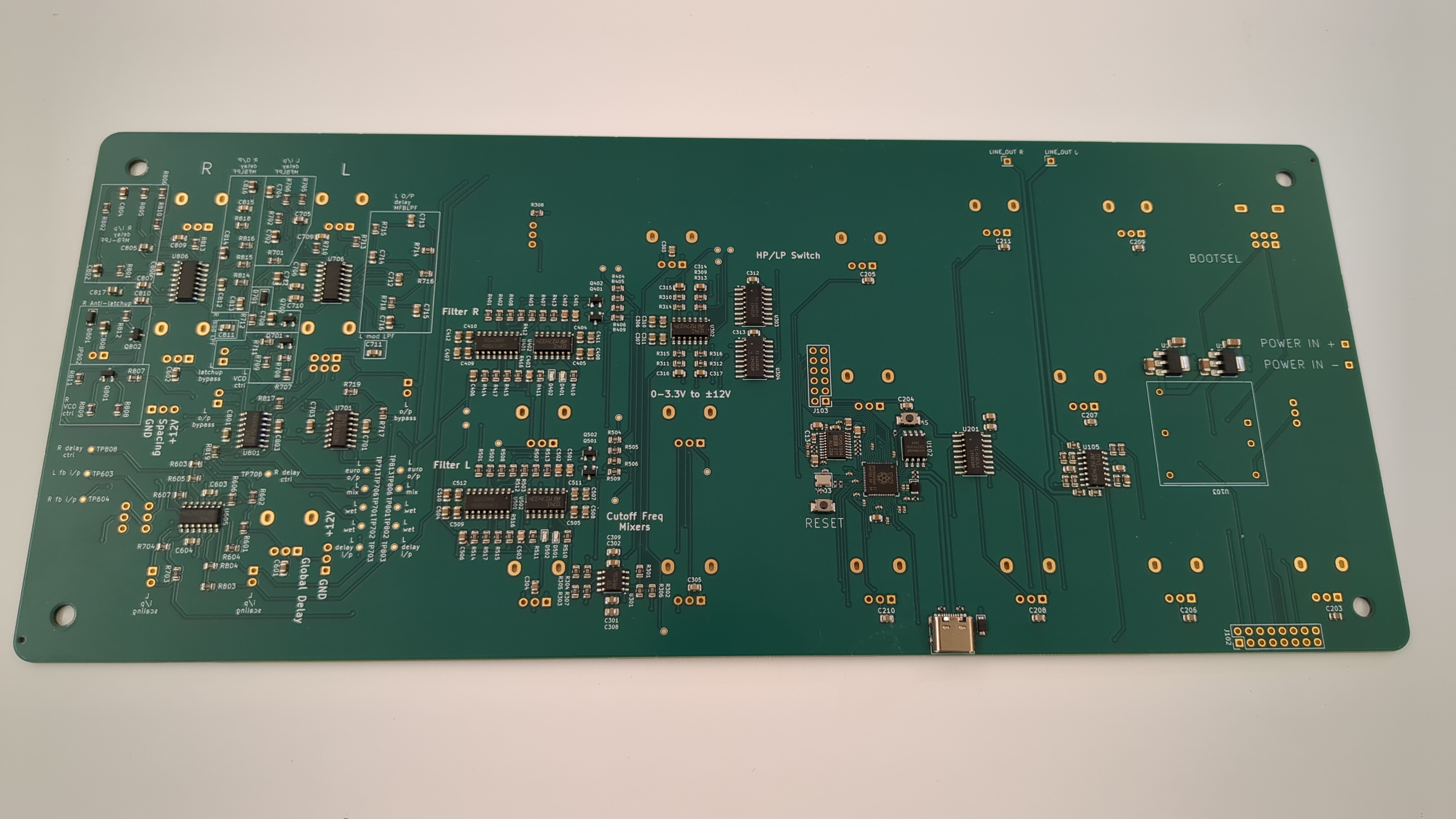
The upper PCB is where most of the action is. It is home to the power, oscillators, filter, and delay circuits.
Power
Power is provided through a DC barrel jack, which is then fed into an integrated DC-DC converter. This provides +12V, -12V, and ground. The +/-12V are used for most of the op-amps in the circuit. The +12V rail also powers two Linear LDO Regulators, providing +5V and +3.3V. The +5V is used by the delay circuit as well as the keyboard, and the +3.3V is used as the digital supply.
Oscillator Subcircuit
The core sound generation of the synthesizer is done by a microcontroller, namely the Raspberry Pi RP2350. This MCU contains a floating point unit, flexible peripherals, and a built-in UF2 bootloader, making it a convenient choice for this application. To provide stereo audio output, the TI PCM5100A, a cheap and high-fidelity audio DAC is used. The RP2350 only includes 4 analog input pins, so to expand this capability a set of analog multiplexers are used. These allow many more analog inputs to be connected. The subcircuit also includes a USB-C connector for uploading firmware.
Filter Subcircuit


Right: The schematic for a single (mono) filter circuit (one of the channels).
The filter circuitry of the SQUID-6 is based on an adaptation by René Schmitz of the MS-20 filter. The Korg MS-20 is an analog synth from the 70s, and the distinct sound of the MS-20 is still well-loved today.
The SQUID-6 features two copies of the MS-20 filter—one for each channel—which can be configured to operate in high-pass or low-pass mode. The cutoff frequency can be tuned approximately across the range of human hearing. The L and R channel can also be offset via a "Spacing" control, allowing for different cutoff frequencies on each side.
The SQUID-6 also features channel-level resonance control. Raising the resonance increases the gain of frequency components near the cutoff frequency. At a high enough resonance, the filter enters self-osciallation, introducing interesting components to the sound.
Delay Subcircuit


The delay of the SQUID-6 is achieved in hardware using a chip called the PT2399. Originally designed in the late 1980ties by Princeton Technology Corp. for the commercial electronics industry the PT2399 found a second life among guitar pedal and synthesizer enthusiasts.
The PT2399 can provide a delay between 38.5-342ms (it can be pushed beyond this if distortion isn't a problem for the application). Thanks to some on die opamps the PT2399 can be configured as either an echo or delay/surround effect without only a handful of passive components. With a little creativity it can also provide more effects such as chorus, flanger, and reverb although more than one PT2399 and additional oscillators might be necessary. If you would like to learn more about the PT2399, Electrosmash has an excellent write up on it.
For our purposed we opted for the echo topology with adjustable feedback that passes through a DPDT switch so the L and Right channel's feedback loops can be cross coupled.
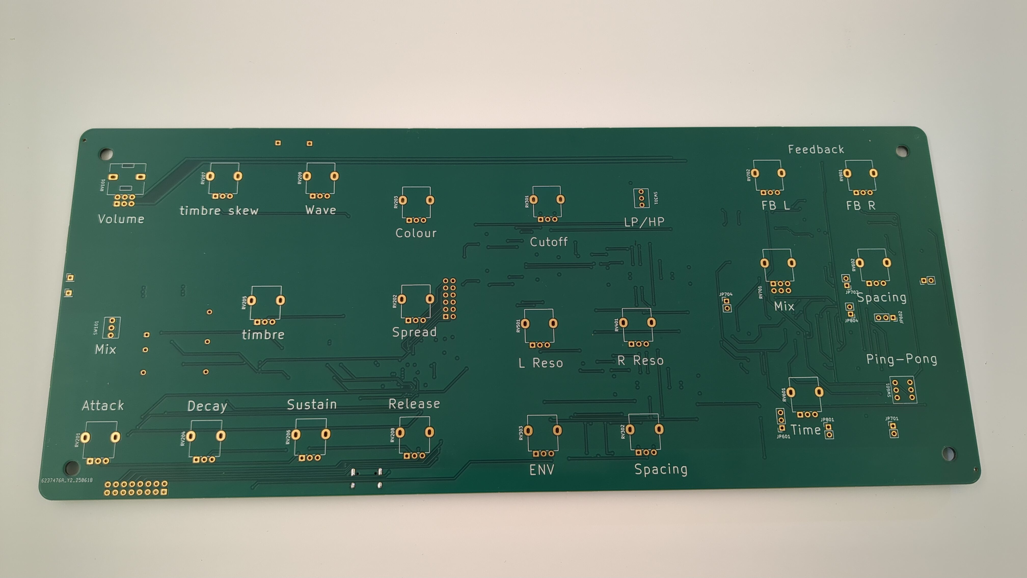
Lower PCB
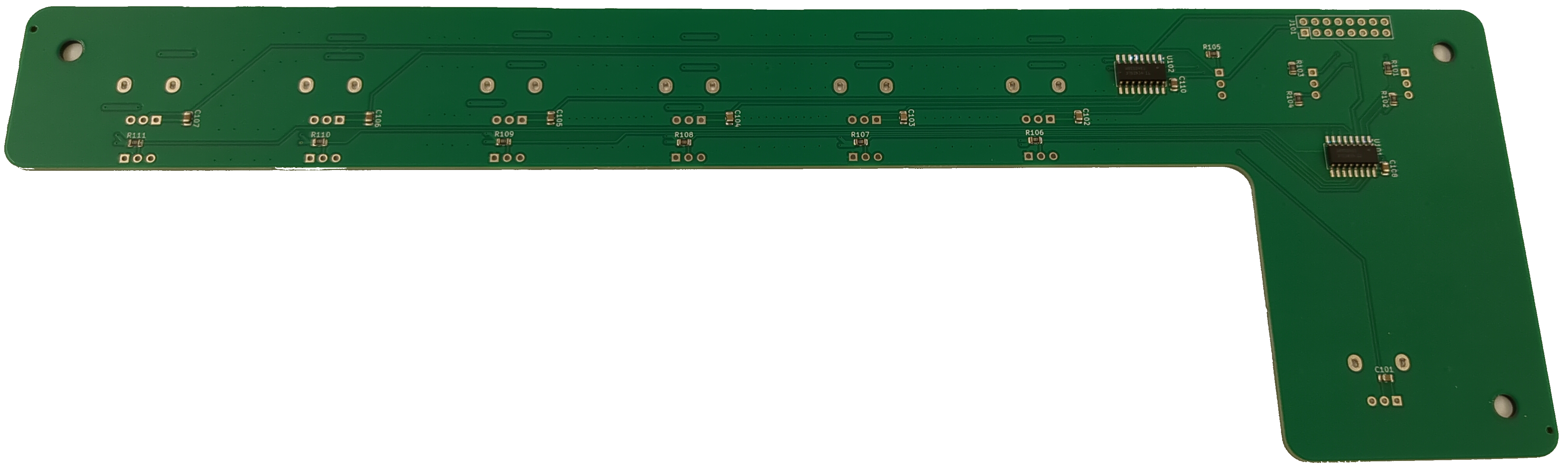
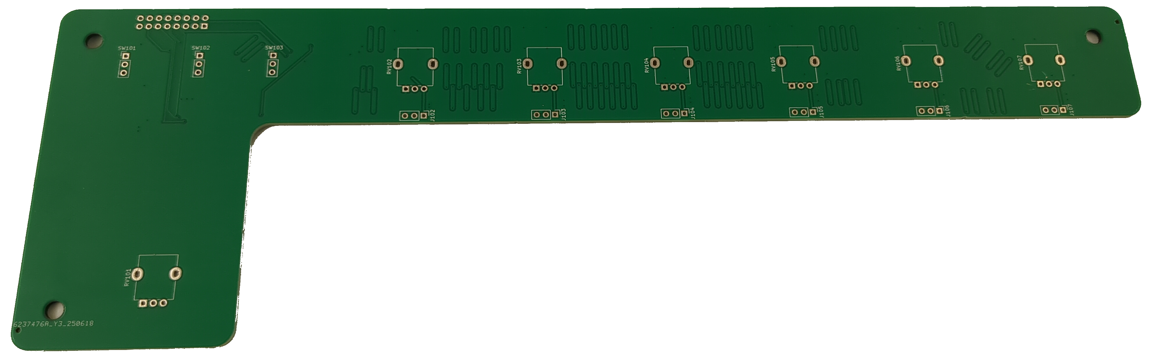
The lower PCB provides connections for SQUID's 6 keys (and associated control pots), along with the modulation switch and BIG mod wheel. The keys are membrane potentiometers, a proprietary invention by SpectraSymbol. Through a fairly simple analog circuit, they allow note on/off information as well as postiion sensing to be read for each key individually. This PCB also includes two analog multiplexers to allow the MCU to read each value from the keys, knobs, and switches.